Introduction
My name is Piyush Nitnaware, I am a client engineer at Spark Creative.co.
Today I am taking the first step towards learning DirectX12 properly, and assembling all my understanding in this blog post.
I have worked on the few projects before where DirectX11 and Directx12 were heavily involved.
And I had very little or no knowledge about these technologies.
While working I gathered few information from here and there and did my job.
Now my understanding about DirectX11/DirectX12 is all over scattered in my head into the broken pieces.
So, I have decided to build the foundation first, so that I can link them together and build the solid understanding around it.
These learning I am going to share through this blog.
About DirectX12
So, I believe that Directx12 applications are just set of rules for GPU given by the CPU.
GPU does not know anything what to do unless CPU tell them to do.
It's like GPUs is the muscular hulk like beast with no brain, and it always needs commands what to do next.
On the other hand, CPUs needs to know how to use GPU's power.
If CPUs doesn't know how to use GPU then the application will end up with nothing.
Check GPU's directX version.
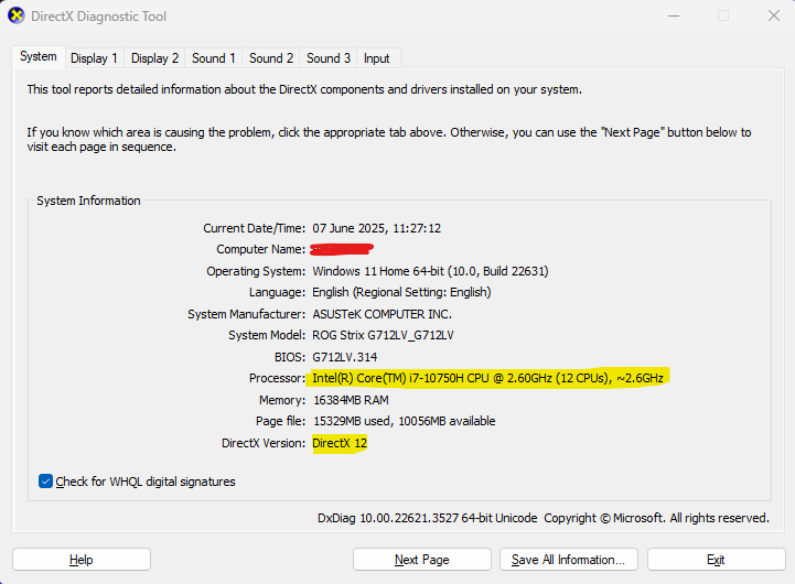
Now the first step is to check whether our graphics card supports DirectX 12 or not.
Run the Directx Diagnostic Tool from the following path.
C:\Windows\System32\dxdiag.exe
It will look something like the below image.
Here we can see which directx version our graphics card supports.
In my case it's DirectX12.
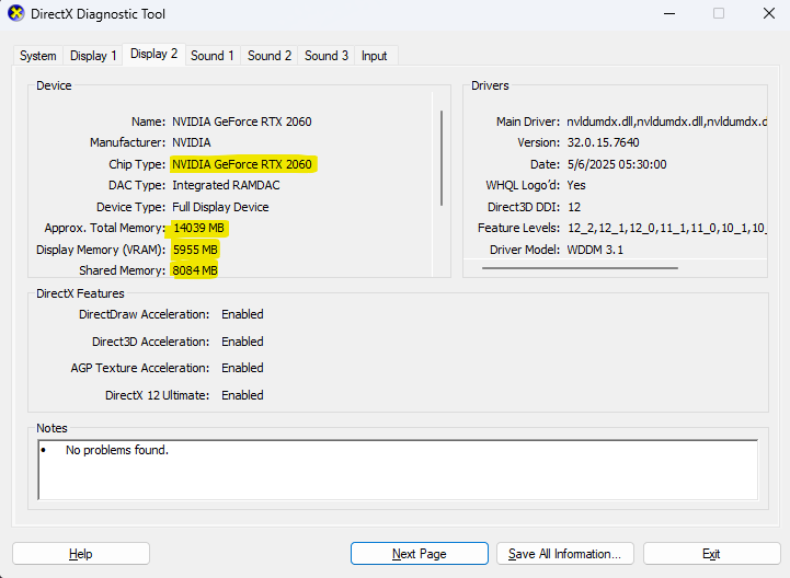
if we go to the display tab then it will show information about graphics card.
Like, name of the graphics card, it's type and memory, etc
Hello world case study
For this blog the below sample project is used.
For me the best way to learn is to study the existing projects and once our brain is ready to understand it's concepts, then we can deep dive into the more advanced stuff.
About the classes
There are main four classes used in this project, those are as follows:
D3D12HelloTriangle.cpp
DXSample.cpp
Main.cpp
Win32Application.cpp
The main bread and butter here is, D3D12HelloTriangle.cpp class, which contains all the code to draw the triangle using DirectX12.
Other classes handles window related functionality like draw window and listens user input events and pass it to D3D12HelloTriangle instance.
D3D12HelloTriangle functions execution
D3D12HelloTriangle is having the following functions which are arranged in the below execution order.
The reason to understand these function calls is just to know at what time which DirectX12 API is being used.
Initialization time (only once):
OnInit()
1. Loads Pipeline
2. Loads assets
Every frame:
OnUpdate()
OnRender()
When program closes (only once):
OnDestroy()
1. Clears handles, etc.
Setup Pipeline
What pipeline setup means, configuring the series of stages to process the graphic data to produce the final image on the screen.
DirectX12 require little more boilerplate code compared to DirectX11 (Assuming that).
Which includes, resource management, synchronization and execution.
Here are the glimpse of the D3D12HelloTriangle::LoadPipeline() function.
Setting debug layer
After enabling debug layers, we will get console error logs at runtime when something is not good as per DirectX12.
※Just for the information DirectX related error logs will start from "D3D12 ERROR:" keyword.
It will provide little more information along with the error, but trust me it's very hard to understand (at least for me).
But hopefully we will understand it someday when we gain little more experience around it :)
ComPtr<ID3D12Debug> debugController;
if (SUCCEEDED(D3D12GetDebugInterface(IID_PPV_ARGS(&debugController))))
{
    debugController->EnableDebugLayer();

    // Enable additional debug layers.
    dxgiFactoryFlags |= DXGI_CREATE_FACTORY_DEBUG;
}
IDXGIFactory4
In Hello Triangle program, IDXGIFactory4 object is being used to create the graphics adaptors and the swap chains.
DXGI stands for, DirectX Graphics Interface.
One side note here, that IDXGIFactory4 is wrapped into the Com pointer. It's like a smart pointer in CPP.
When holder count becomes 0, then the object will get destroyed automatically.
IDXGIFactory4 is used to create the graphics adaptor and adaptor is used to create the device.
Yes, we need this device all the time to do crazy stuff in our DirectX 12 program.
To render something via DirectX API we need to determine the adapter first. That is exactly IDXGIFactory4 interface will do for us. [1]
ThrowIfFailed(D3D12CreateDevice(
    warpAdapter.Get(),
    D3D_FEATURE_LEVEL_11_0,
    IID_PPV_ARGS(&m_device)
    ));
Why we need this device if you may ask.
well, we need device to create command, allocators, command list, command queue, fences, resources, pipeline state objects, heaps, root signatures, and bla bla.
So this device is the main person who has all the abilities to do bubbly bubbly stuff in our application.
Command Queue
ID3D12CommandQueue is the interface for command queue.
In simple words, the command queue is the delivery person who delivers our rendering commands to the GPU.
There are few types of command types, out of that D3D12_COMMAND_LIST_TYPE_DIRECT allows all the operations, whether they are graphics, compute or copy.
D3D12_COMMAND_QUEUE_DESC queueDesc = {};
queueDesc.Flags = D3D12_COMMAND_QUEUE_FLAG_NONE;
queueDesc.Type = D3D12_COMMAND_LIST_TYPE_DIRECT;

ThrowIfFailed(m_device->CreateCommandQueue(&queueDesc, IID_PPV_ARGS(&m_commandQueue)));
Command Allocator
To submit rendering commands a command list is used which gonna submit in the command queue.
And command queue will transport these rendering commands in command list to the GPU.
In the previous version of D3D (Directx11) there was an immediate submission of work, but that support has been replaced with command queue and command list which also enables the possibility of multi-threaded rendering.
ThrowIfFailed(m_device->CreateCommandAllocator(D3D12_COMMAND_LIST_TYPE_DIRECT, IID_PPV_ARGS(&m_commandAllocator)));
Swap chain
The next setup stage is to create swap chains.
To create swap chains we need to define lots of properties.
below is the code snippet from Hello Triangle example.
    DXGI_SWAP_CHAIN_DESC1 swapChainDesc = {};
    swapChainDesc.BufferCount = FrameCount;
    swapChainDesc.Width = m_width;
    swapChainDesc.Height = m_height;
    swapChainDesc.Format = DXGI_FORMAT_R8G8B8A8_UNORM;
    swapChainDesc.BufferUsage = DXGI_USAGE_RENDER_TARGET_OUTPUT;
    swapChainDesc.SwapEffect = DXGI_SWAP_EFFECT_FLIP_DISCARD;
    swapChainDesc.SampleDesc.Count = 1;

    ComPtr<IDXGISwapChain1> swapChain;
    ThrowIfFailed(factory->CreateSwapChainForHwnd(
        m_commandQueue.Get(),        // Swap chain needs the queue so that it can force a flush on it.
        Win32Application::GetHwnd(),
        &swapChainDesc,
        nullptr,
        nullptr,
        &swapChain
        ));
The concept of swap chain, is that we always draw on the buffer which is not visible on the screen (called as back buffer).
Once our drawing done on the back buffer, then we replace it with the currently visible buffer, this transition is called buffer swapping.
After this swapping done, the last frame's front buffer becomes our back buffer and back buffer becomes the front buffer.
These buffer swapping happens all the time and our goal is to swap these buffer as fast as we can.
If we are are getting 60 FPS, that means the buffers have swapped 60 times in one second.
Creating render target views
Once swap chain is done, we will have to create render targets so that our shaders can write the output to it.
As per my knowledge we can create upto 8 render targets.
Our swap chain is ready but DirectX12 doesn't know where to write our shader output, we are defining just that via render target which is also a type of texture.
To allocate memory block for render target or any runtime asset, D3DX provides descriptors.
Below are the types of descriptor heaps:
1. D3D12_DESCRIPTOR_HEAP_TYPE_CBV_SRV_UAV
2. D3D12_DESCRIPTOR_HEAP_TYPE_SAMPLER
3. D3D12_DESCRIPTOR_HEAP_TYPE_RTV
4. D3D12_DESCRIPTOR_HEAP_TYPE_DSV
To create render target view D3D12_DESCRIPTOR_HEAP_TYPE_RTV is used.
// Describe and create a render target view (RTV) descriptor heap.
D3D12_DESCRIPTOR_HEAP_DESC rtvHeapDesc = {};
rtvHeapDesc.NumDescriptors = FrameCount;
rtvHeapDesc.Type = D3D12_DESCRIPTOR_HEAP_TYPE_RTV;
rtvHeapDesc.Flags = D3D12_DESCRIPTOR_HEAP_FLAG_NONE;
ThrowIfFailed(m_device->CreateDescriptorHeap(&rtvHeapDesc, IID_PPV_ARGS(&m_rtvHeap)));

m_rtvDescriptorSize = m_device->GetDescriptorHandleIncrementSize(D3D12_DESCRIPTOR_HEAP_TYPE_RTV);
Note that in the above code, we have created descriptor heap using D3D12_DESCRIPTOR_HEAP_DESC description, and assigns this newly created descriptor instance to m_rtvHeap variable.
Descriptor heaps are just the block of memory with no actual data in it.
CD3DX12_CPU_DESCRIPTOR_HANDLE rtvHandle(m_rtvHeap->GetCPUDescriptorHandleForHeapStart());

//Create a RTV for each frame.
for (UINT n = 0; n < FrameCount; n++)
{
   ThrowIfFailed(m_swapChain->GetBuffer(n, IID_PPV_ARGS(&m_renderTargets[n])));
   m_device->CreateRenderTargetView(m_renderTargets[n].Get(), nullptr, rtvHandle);
   rtvHandle.Offset(1, m_rtvDescriptorSize);
}
To allocate the memory block for the render target view D3D12_DESCRIPTOR_HEAP_DESC structure is used,
and these heap memory accessed by the handles for which CD3DX12_CPU_DESCRIPTOR_HANDLE as used.
It provides functionality for cpu to manipulate the data in the heap.
Summery
In this section, only the initialization stuff has done in a DirectX12 way.
This initialization have to happen only once when the application boots up or any loading of scene.
Below are the simple checklist of what has happened in the pipeline setup.
1. At the very beginning a debug layer is enabled so that we can get logs if something goes wrong.
2. AIDXGIFactory4 object was created, later graphics adaptor was requested from this factory object.
2.1 These adaptor provides information about our graphics hardware, also sometimes during development these adaptors can be a software which is called as WARP (Windows Advanced Rasterization Platform).
3. For rendering command queue and command lists objects are created.
4. Then swap chain was created and also render target views were created along with their buffers into the memory using descriptor heaps and descriptor handles.
Load assets
LoadAssets() function also gets called from the OnInit() function, which means this function also execute once in the application and sets necessary variables which we might require during rendering calls.
Setting Root Signatures
In Hello Triangle application, an empty root signature is set, probably just because this is a very basic application and it might not require more states to set.
 CD3DX12_ROOT_SIGNATURE_DESC rootSignatureDesc;
 rootSignatureDesc.Init(0, nullptr, 0, nullptr, D3D12_ROOT_SIGNATURE_FLAG_ALLOW_INPUT_ASSEMBLER_INPUT_LAYOUT);

 ComPtr<ID3DBlob> signature;
 ComPtr<ID3DBlob> error;
 ThrowIfFailed(D3D12SerializeRootSignature(&rootSignatureDesc, D3D_ROOT_SIGNATURE_VERSION_1, &signature, &error));
 ThrowIfFailed(m_device->CreateRootSignature(0, signature->GetBufferPointer(), signature->GetBufferSize(), IID_PPV_ARGS(&m_rootSignature)));
Root signatures defines how shaders interact with resources during rendering. This is an basic layout structure which instructs the GPU how the resources are being used in the shaders. [2]
With the root signature we can define the following properties:
1. We can set which resource belongs to which shader part. For example, vertex shader (D3D12_SHADER_VISIBILITY_VERTEX) or pixel shader (D3D12_SHADER_VISIBILITY_PIXEL).
{ .ShaderVisibility = D3D12_SHADER_VISIBILITY_VERTEX, .ParameterType = D3D12_ROOT_PARAMETER_TYPE_32BIT_CONSTANTS, .Constants = { .Num32BitValues = 50 } }, [3]
2. We can tell GPU how to read data from the texture using sampler descriptions. For example how to read U and V data (D3D12_TEXTURE_ADDRESS_MODE_WRAP, D3D12_TEXTURE_ADDRESS_MODE_WRAP)
pStaticSamplers = (D3D12_STATIC_SAMPLER_DESC[1]) {
            { .ShaderVisibility = D3D12_SHADER_VISIBILITY_PIXEL, .Filter = D3D12_FILTER_ANISOTROPIC, .AddressU = D3D12_TEXTURE_ADDRESS_MODE_WRAP,
                .AddressV = D3D12_TEXTURE_ADDRESS_MODE_WRAP, .AddressW = D3D12_TEXTURE_ADDRESS_MODE_WRAP, .MaxLOD = 1000.0f, .MaxAnisotropy = 16 }
Create ID3D12PipelineState
Once the root signature is in place, the next step is to use this root signature to create the pipeline.
Creating pipeline means join the root signature description with the shader so that GPU will know what our expectation from the shader.
Here is the shader code which is used in Hello Triangle application.
Shaders
You can see the shader in the below path.
D3D12HelloTriangle/Assets/Shaders/Shaders.hlsl
the content of the shader as follows:
struct PSInput
{
    float4 position : SV_POSITION;
    float4 color : COLOR;
};

PSInput VSMain(float4 position : POSITION, float4 color : COLOR)
{
    PSInput result;

    result.position = position;
    result.color = color;

    return result;
}

float4 PSMain(PSInput input) : SV_TARGET
{
    return input.color;
}
There is nothing fancy going on in this shader.
In the vertex shader (VSMain) the position and color values passed to the pixel shader. To pass these values, PsInput struct is used.
Then pixel shader (PSMain) reads the properties from the PsInput struct, process that data and returns the color value as it is.
Compile she shaders
The shader needs to be compiled into the bytecode in order to use with GPU.
I am assuming this requirement just because there are other graphics libraries too, for example, OpenGL, Vulkan etc.
This way GPU might take the input as same for all the libraries.
Apart from this GPU also might do some optimizations on their end, so the basic requirement is to be a ByteCode format.
There are two types of shader compilers in DirectX12.
1. Old Compiler - FXC
2. New Compiler - DXC
New compilers only works with the upgraded systems, and old compiler can work on all the systems.
Below is the code snippet from Hello Triangle application.
To compile the shaders D3DCompileFromFile function is used, which is a part of d3dcompiler.h/d3dcompiler.lib DirectX library.
One more point is that to compile the shaders, old compiler (FXC) is used.
ComPtr<ID3DBlob> vertexShader;
ComPtr<ID3DBlob> pixelShader;

#if defined(_DEBUG)
// Enable better shader debugging with the graphics debugging tools.
UINT compileFlags = D3DCOMPILE_DEBUG | D3DCOMPILE_SKIP_OPTIMIZATION;
#else
UINT compileFlags = 0;
#endif
ThrowIfFailed(D3DCompileFromFile(GetAssetFullPath(L"shaders.hlsl").c_str(), nullptr, nullptr, "VSMain", "vs_5_0", compileFlags, 0, &vertexShader, nullptr));
ThrowIfFailed(D3DCompileFromFile(GetAssetFullPath(L"shaders.hlsl").c_str(), nullptr, nullptr, "PSMain", "ps_5_0", compileFlags, 0, &pixelShader, nullptr));
Here are the parameters.
1. GetAssetFullPath(L"shaders.hlsl").c_str()
Is the full shader file path.
2. VSMain/PSMain
The entry point of the shader function.
For vertex sahders "VSMain" is the entry point and for pixel shaders "PSMain" is the entry point.
3. vs_5_0/ps_5_0
This is the parameters denotes the target shader model.
#_5_0 is the shader model 5.0 of vs and ps shader respectively.
4. Compile flags
Compile flags are the constants to specify how the compilers should compiles the HLSL shader code.
5. vertexShader/pixelShader
These two are the variables of ComPtr
Shader Layout
To create the pipeline, input assembly layout need to be set.
Following the code snippet from Hello Triangle application.
// Define the vertex input layout.
D3D12_INPUT_ELEMENT_DESC inputElementDescs[] =
{
    { "POSITION", 0, DXGI_FORMAT_R32G32B32_FLOAT, 0, 0, D3D12_INPUT_CLASSIFICATION_PER_VERTEX_DATA, 0 },
    { "COLOR", 0, DXGI_FORMAT_R32G32B32A32_FLOAT, 0, 12, D3D12_INPUT_CLASSIFICATION_PER_VERTEX_DATA, 0 }
};
This layout needs to exactly match with the VSMain's function parameters.
VSMain(float4 position : POSITION, float4 color : COLOR)
A structure can also be used as a VSMain parameter just like PsInput.
In that case the layout needs to be matched with that struct.
Parameters are as follows:
1. POSITION/COLOR
POSITION/SCALE are the predefined semantics which are used to define the layout.
There are other bunch of semantics which we can set as per the requirements.
For example BINORMAL can be used to indicated normal vector.
2. Semantic Index
The second parameter is the semantic index.
The semantic index is needed where there is more than one element with the same semantic.
3. DXGI Format
DXGI formats are the data format.
DXGI_FORMAT_R32G32B32_FLOAT is being used as a DXGI format.
These formats are self explanatory, as for R32G32B32 all the RGBA channels are 32 bits.
There are the following types of sub formats to choose from.
Choosing the right format is crucial for correct data bindings and performance.
DXGI_FORMAT_UNKNOWN
This format generally being used as a placeholder or for uninitialized formats.
Better to avoid using this in the production since resource creation or binding is not possible.
_TYPELESS
Typeless format can be used for the resources whose resource size is known but the data type is not yet defined.
An application or shader later needs to resolve this format.
_UINT
This is An unsigned integer format.
_SINT
An integer value from -ve to +ve.
_UNORM
This is a normalized integer format mapped whose value can be from 0-1.
_SNORM
A normalized integer format whose value can be from -1 to 1.
4. Input Slot
There might be multiple properties with the same semantics, to distinguish them from each other, input slot value can be set.
For the first element for the same semantics is 0. As we use the same element that much times this value needs to be set.
for example,
TEXCOORD, 0
TEXCOORD, 1
TEXCOORD, 2
5. Alignment Byte Offset
This parameter defines which memory layer the data needs to set.
in the above code snippet, for POSITION 0 is set but 12 is set for the COLOR.
If we look at the DXGI format, POSITION has R32G32B32 datatype, which means 3 floats of 4 bytes.
So for the next element of COLOR needs to set after POSITION data which means after 12 bytes.
6. Input Classification
Input classification defines the input type whether the input is per vertex or per instance.
The default is per vertex, for per instance I believe that we need to make changes accordingly in the entire programming structure.
7. Input data step rate
This is must be 0 for per vertex data.
Creating graphics pipeline state object
Following is the code snippet from the same Hello Triangle example.
By this code the pipeline object is being created, to do that all the parameters are used.
//Describe and create the graphics pipeline state object (PSO).
D3D12_GRAPHICS_PIPELINE_STATE_DESC psoDesc = {};
psoDesc.InputLayout = { inputElementDescs, _countof(inputElementDescs) };
psoDesc.pRootSignature = m_rootSignature.Get();
psoDesc.VS = CD3DX12_SHADER_BYTECODE(vertexShader.Get());
psoDesc.PS = CD3DX12_SHADER_BYTECODE(pixelShader.Get());
psoDesc.RasterizerState = CD3DX12_RASTERIZER_DESC(D3D12_DEFAULT);
psoDesc.BlendState = CD3DX12_BLEND_DESC(D3D12_DEFAULT);
psoDesc.DepthStencilState.DepthEnable = FALSE;
psoDesc.DepthStencilState.StencilEnable = FALSE;
psoDesc.SampleMask = UINT_MAX;
psoDesc.PrimitiveTopologyType = D3D12_PRIMITIVE_TOPOLOGY_TYPE_TRIANGLE;
psoDesc.NumRenderTargets = 1;
psoDesc.RTVFormats[0] = DXGI_FORMAT_R8G8B8A8_UNORM;
psoDesc.SampleDesc.Count = 1;
ThrowIfFailed(m_device->CreateGraphicsPipelineState(&psoDesc, IID_PPV_ARGS(&m_pipelineState)));
1. Input Layout
This is the input layout for our target shader expects (POSITION, COLOR properties).
2. Root Signature
The description for the GPU that how the shader gonna use the resources.
3. VS
Compiled version of the vertex shader.
D3D12HelloTriangle/Assets/Shaders/Shaders.hlsl -> VSMain
4. PS
Compiled version of the pixel shader.
D3D12HelloTriangle/Assets/Shaders/Shaders.hlsl -> PSMain
5. RasterizerState
This variable contains various information about the rasterization state.
In this Hello Triangle application the default values are used using CD3DX12_RASTERIZER_DESC(D3D12_DEFAULT).
Default values are good for simple application like this but for the more complex applications where transparencies are involved then setting this rasterization values are very crucial.
6. Depth Enable
Here, the value if false.
If this is true then the depth buffer also should had to set in order to draw into the depth buffer.
7. Stencil Enable
Stencil is also set to false.
8. Sample Mask
Sample Mask is required for the multi-sampling.
We will take a look at this in the later case studies.
9. Primitive Topology Type
This is the topology that instructs how to organize the vertices.
D3D12_PRIMITIVE_TOPOLOGY_TYPE_TRIANGLE is used in this example.
I believe that most of the times we have to use this topology only.
Sine it will form a triangular mesh by using set of 3 vertex points.
10. Num Rnder Targets
This is the number of render targets.
Here, only one render target being used.
Multiple render targets could be used in various applications based on the requirements, for example.
Render Targets to store the the following information.
1. Normal Data
2. Depth Value
11. RTVFormats
DXGI_FORMAT_R8G8B8A8_UNORM format is set here.
According to MSDN, this is a 32-bit normalized RGBA channel values.
I think enough to store the color data.
12. Sample Desc.Count
This value is also for the multi sampling, and this value must be same as NumRenderTargets.
Creating Command List
Command queue was created previously and also set it for the swap chains.
But in order to submit commands to the command queue, command list is used.
Following is the code snippet to create command list.
// Create the command list.
ThrowIfFailed(m_device->CreateCommandList(0, D3D12_COMMAND_LIST_TYPE_DIRECT, m_commandAllocator.Get(), m_pipelineState.Get(), IID_PPV_ARGS(&m_commandList)));

// Command lists are created in the recording state, but there is nothing
// to record yet. The main loop expects it to be closed, so close it now.
ThrowIfFailed(m_commandList->Close());
Setting the triangle vertex buffers
In order to draw the triangle on the screen, GPU needs to know what to draw.
That is exactly set here.
// Define the geometry for a triangle.
Vertex triangleVertices[] =
{
    { { 0.0f, 0.25f * m_aspectRatio, 0.0f }, { 1.0f, 0.0f, 0.0f, 1.0f } },
    { { 0.25f, -0.25f * m_aspectRatio, 0.0f }, { 0.0f, 1.0f, 0.0f, 1.0f } },
    { { -0.25f, -0.25f * m_aspectRatio, 0.0f }, { 0.0f, 0.0f, 1.0f, 1.0f } }
};

const UINT vertexBufferSize = sizeof(triangleVertices);

// Note: using upload heaps to transfer static data like vert buffers is not
// recommended. Every time the GPU needs it, the upload heap will be marshalled
// over. Please read up on Default Heap usage. An upload heap is used here for
// code simplicity and because there are very few verts to actually transfer.
ThrowIfFailed(m_device->CreateCommittedResource(
    &CD3DX12_HEAP_PROPERTIES(D3D12_HEAP_TYPE_UPLOAD),
    D3D12_HEAP_FLAG_NONE,
    &CD3DX12_RESOURCE_DESC::Buffer(vertexBufferSize),
    D3D12_RESOURCE_STATE_GENERIC_READ,
    nullptr,
    IID_PPV_ARGS(&m_vertexBuffer)));

// Copy the triangle data to the vertex buffer.
UINT8* pVertexDataBegin;
CD3DX12_RANGE readRange(0, 0);        // We do not intend to read from this resource on the CPU.
ThrowIfFailed(m_vertexBuffer->Map(0, &readRange, reinterpret_cast<void**>(&pVertexDataBegin)));
memcpy(pVertexDataBegin, triangleVertices, sizeof(triangleVertices));
m_vertexBuffer->Unmap(0, nullptr);

// Initialize the vertex buffer view.
m_vertexBufferView.BufferLocation = m_vertexBuffer->GetGPUVirtualAddress();
m_vertexBufferView.StrideInBytes = sizeof(Vertex);
m_vertexBufferView.SizeInBytes = vertexBufferSize;
In the triangleVertices array, the vertex information needs to set.
To upload the resource data to the GPU CreateCommittedResource function is used.
Also, D3D12_HEAP_TYPE_UPLOAD this parameter asks the device to upload the data to the GPU.
There are two types of ram memory, system ram and GPU ram (VRAM), the process of passing the data to VRAM is called staging.
D3D12_HEAP_TYPE_UPLOAD is a copy data operation so that shader can access them from VRAM.
However, this is not the recommended way to do it, instead the author suggests to use D3D12_HEAP_TYPE_DEFAULT heap type.
And D3D12_HEAP_TYPE_UPLOAD is used here just for the code simplicity.
During CreateCommittedResource function call, m_vertexBuffer was initialized which links the memory GPU memory address.
And to set the data later, a CPP memset function is being used.
memcpy(pVertexDataBegin, triangleVertices, sizeof(triangleVertices));
m_vertexBuffer->Unmap(0, nullptr);
Once the GPU memory is set, the GPU memory layout is being set using D3D12_VERTEX_BUFFER_VIEW.
This memory layout just points to the buffer block using, the buffer start location (BufferLocation), strides and size of the memory block.
m_vertexBufferView.BufferLocation = m_vertexBuffer->GetGPUVirtualAddress();
m_vertexBufferView.StrideInBytes = sizeof(Vertex);
m_vertexBufferView.SizeInBytes = vertexBufferSize;
Fence
DirectX12 is a low level API that provides more flexibility and fine-grained control on the underlaying layout, resulting in better resource utilization, but requires the application to manage resources and synchronization.
For that reason DirectX 12 uses the concept of Fences.
Fences can be used one of two ways to sync the CPU to the GPU or to sync between two queues.
For syncing WaitForPreviousFrame() function is used to check if both have or reached the same state.
ThrowIfFailed(m_device->CreateFence(0, D3D12_FENCE_FLAG_NONE, IID_PPV_ARGS(&m_fence)));
m_fenceValue = 1;

// Create an event handle to use for frame synchronization.
m_fenceEvent = CreateEvent(nullptr, FALSE, FALSE, nullptr);
if (m_fenceEvent == nullptr)
{
   ThrowIfFailed(HRESULT_FROM_WIN32(GetLastError()));
}

// Wait for the command list to execute; we are reusing the same command
// list in our main loop but for now, we just want to wait for setup to
// complete before continuing.
WaitForPreviousFrame();
WaitForPreviousFrame
void D3D12HelloTriangle::WaitForPreviousFrame()
{
    // WAITING FOR THE FRAME TO COMPLETE BEFORE CONTINUING IS NOT BEST PRACTICE.
    // This is code implemented as such for simplicity. The D3D12HelloFrameBuffering
    // sample illustrates how to use fences for efficient resource usage and to
    // maximize GPU utilization.

    // Signal and increment the fence value.
    const UINT64 fence = m_fenceValue;
    ThrowIfFailed(m_commandQueue->Signal(m_fence.Get(), fence));
    m_fenceValue++;

    // Wait until the previous frame is finished.
    if (m_fence->GetCompletedValue() < fence)
    {
        ThrowIfFailed(m_fence->SetEventOnCompletion(fence, m_fenceEvent));
        WaitForSingleObject(m_fenceEvent, INFINITE);
    }

    m_frameIndex = m_swapChain->GetCurrentBackBufferIndex();
}
In the below example, use practical use case is explained in simple pseudocode example.
let's assume we have GPU work A, GPU work B and Compute work C and Compute work D.
Compute work C relies on some resource GPU A must process.
And Compute work D relies on the GPU work B.
The we can submit the following queue.
Fence p =0

DrawInstance(GPU work A)
p->Signal(1)

DrawInstance(GPU work B)
p->Signal(2)

//Then on the compute queue
Wait(p, 1)
Dispatch(Compute work C)

Wait(p, 2)
Dispatch(Compute work D)
As we can clearly see that Compute work C and Compute work D are waiting for P value to be 1 and 2 respectively.
OnRender() function
OnRender() function executes every frame.
All the rendering commands will be populated to submitted to the GPU in this function.
Below is the code snippet of OnRender() function of D3D12HelloTriangle example.
void D3D12HelloTriangle::OnRender()
{
    // Record all the commands we need to render the scene into the command list.
    PopulateCommandList();

    // Execute the command list.
    ID3D12CommandList* ppCommandLists[] = { m_commandList.Get() };
    m_commandQueue->ExecuteCommandLists(_countof(ppCommandLists), ppCommandLists);

    // Present the frame.
    ThrowIfFailed(m_swapChain->Present(1, 0));

    WaitForPreviousFrame();
}
Let's take a look at PopulateCommandList() function and try to understand what is happening there.
// Command list allocators can only be reset when the associated
// command lists have finished execution on the GPU; apps should use
// fences to determine GPU execution progress.
ThrowIfFailed(m_commandAllocator->Reset());

// However, when ExecuteCommandList() is called on a particular command
// list, that command list can then be reset at any time and must be before
// re-recording.
ThrowIfFailed(m_commandList->Reset(m_commandAllocator.Get(), m_pipelineState.Get()));

// Set necessary state.
m_commandList->SetGraphicsRootSignature(m_rootSignature.Get());
m_commandList->RSSetViewports(1, &m_viewport);
m_commandList->RSSetScissorRects(1, &m_scissorRect);

// Indicate that the back buffer will be used as a render target.
m_commandList->ResourceBarrier(1, &CD3DX12_RESOURCE_BARRIER::Transition(m_renderTargets[m_frameIndex].Get(), D3D12_RESOURCE_STATE_PRESENT, D3D12_RESOURCE_STATE_RENDER_TARGET));

CD3DX12_CPU_DESCRIPTOR_HANDLE rtvHandle(m_rtvHeap->GetCPUDescriptorHandleForHeapStart(), m_frameIndex, m_rtvDescriptorSize);
m_commandList->OMSetRenderTargets(1, &rtvHandle, FALSE, nullptr);

// Record commands.
const float clearColor[] = { 0.0f, 0.2f, 0.4f, 1.0f };
m_commandList->ClearRenderTargetView(rtvHandle, clearColor, 0, nullptr);
m_commandList->IASetPrimitiveTopology(D3D_PRIMITIVE_TOPOLOGY_TRIANGLELIST);
m_commandList->IASetVertexBuffers(0, 1, &m_vertexBufferView);
m_commandList->DrawInstanced(3, 1, 0, 0);

// Indicate that the back buffer will now be used to present.
m_commandList->ResourceBarrier(1, &CD3DX12_RESOURCE_BARRIER::Transition(m_renderTargets[m_frameIndex].Get(), D3D12_RESOURCE_STATE_RENDER_TARGET, D3D12_RESOURCE_STATE_PRESENT));

ThrowIfFailed(m_commandList->Close());
Every time before submitting any command, reset the command allocator and command list, it will allocate a block of memory, and if that block is filled up it will request more from the allocator.
Then prepare the command list.
m_commandList->SetGraphicsRootSignature(m_rootSignature.Get());
m_commandList->RSSetViewports(1, &m_viewport);
m_commandList->RSSetScissorRects(1, &m_scissorRect);
First, set the root signature followed by viewport set and scissor rect.
There is no scissoring happen, so m_scissorRect value is exactly matches with the monitor's height and width.
Then, to make sure to write onto the back buffer.
Added a resource barrier and waiting until the current frame is displayed.
Once this transition is done, we are ready to reset the data of back buffer and start drawing onto it.
m_commandList->ResourceBarrier(1, &CD3DX12_RESOURCE_BARRIER::Transition(m_renderTargets[m_frameIndex].Get(), D3D12_RESOURCE_STATE_PRESENT, D3D12_RESOURCE_STATE_RENDER_TARGET));
The next step is to bind the render target on which we are going to draw.
CD3DX12_CPU_DESCRIPTOR_HANDLE rtvHandle(m_rtvHeap->GetCPUDescriptorHandleForHeapStart(), m_frameIndex, m_rtvDescriptorSize);
m_commandList->OMSetRenderTargets(1, &rtvHandle, FALSE, nullptr);
One this little setup is done, it's time add the actual rendering commands.
// Record commands.
const float clearColor[] = { 0.0f, 0.2f, 0.4f, 1.0f };
m_commandList->ClearRenderTargetView(rtvHandle, clearColor, 0, nullptr);
m_commandList->IASetPrimitiveTopology(D3D_PRIMITIVE_TOPOLOGY_TRIANGLELIST);
m_commandList->IASetVertexBuffers(0, 1, &m_vertexBufferView);
m_commandList->DrawInstanced(3, 1, 0, 0);
First, clears the render target.
Set the topology (a way of process mesh in GPU), set the mesh vertices and at last add a draw call for rendering.
Once we done with setting and placing draw calls, it's time to present our frame.
Then at the end close the command list.
I think, when we know that we are done with populating the command list, closing it in the mindset that we are not adding any command to it.
m_commandList->ResourceBarrier(1, &CD3DX12_RESOURCE_BARRIER::Transition(m_renderTargets[m_frameIndex].Get(), D3D12_RESOURCE_STATE_RENDER_TARGET, D3D12_RESOURCE_STATE_PRESENT));

ThrowIfFailed(m_commandList->Close());
So our command list is populated and also requested to present once it's done.
Now request the swap chain object to present.
ThrowIfFailed(m_swapChain->Present(1, 0));

WaitForPreviousFrame();
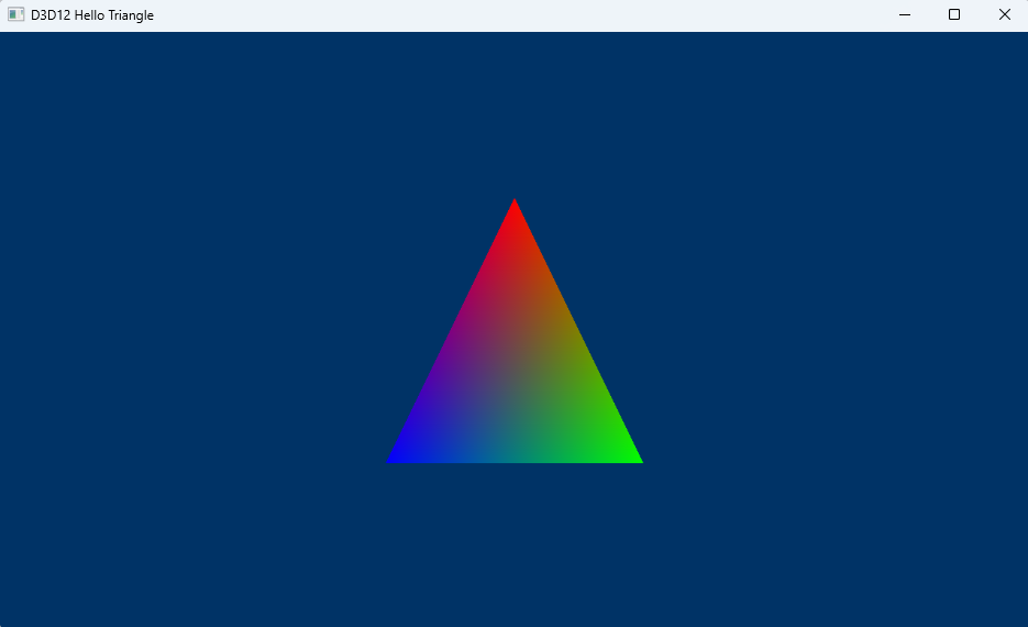
The output will looks like below:
Online References
Adaptors
1. Factory and adapters
Root Signatures
2. Root Signature - Serverspace.io
Pipeline
3. Root signature and pipeline state
Shader Compiler related
4. Two Shader Compilers of Direct3D 12
5. How To Compile a Shader - Win32 apps | Microsoft Learn
6. D3DCOMPILE Constants (D3DCompiler.h) - Win32 apps | Microsoft Learn
7. Semantics - Win32 apps | Microsoft Learn
DXGI Formats
8. DXGI_FORMAT (dxgiformat.h) - Win32 apps | Microsoft Learn
Blending States
9. 02.A - Blending | P.A. Minerva
Other Tutorials
10. 04. Drawing! - Braynzar Soft
Data upload to VRAM
11. Effective Use of the New D3D12_HEAP_TYPE_GPU_UPLOAD - AMD GPUOpen
Resource Barriers
12. Resource Barriers - Prysm documentation